HPDC Die Design and Manufacturing
Objective
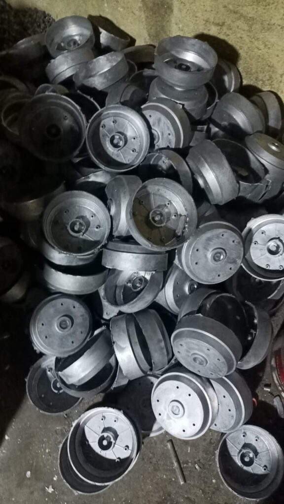
To design and develop a High Pressure Die Casting (HPDC) die for aluminum components, reducing costs by replacing expensive aluminum block machining and eliminating blow holes commonly found in sand-cast parts, resulting in higher quality and more efficient production.
Requirement
- Define the detailed geometry, dimensions, and tolerances of the aluminum component to be produced.
- Understand the functional requirements of the part, including mechanical properties, surface finish, and performance expectations.
- Select the appropriate aluminum alloy for the casting process based on the desired mechanical properties, such as strength, ductility, and corrosion resistance.
- Ensure compatibility between the die material and the chosen aluminum alloy to prevent wear and tear on the die.
- Identify optimal gate locations, runner systems, and venting to prevent defects like air entrapment, porosity, and incomplete filling.
- Plan for an effective ejection system that ensures smooth removal of the cast part without damaging it or the die.
- Select high-strength tool steels or other appropriate die materials capable of withstanding high temperatures and pressures.
- Account for shrinkage and warpage during cooling by adjusting the die dimensions and designing the parting line, draft angles, and tolerances accordingly.
- Optimize the die design for manufacturability, ensuring ease of production, assembly, and maintenance.
- Plan for lead times in die construction, including procurement of materials, machining, assembly, and testing.
Process Step
Study NADCA Guidelines:
- Thoroughly review the North American Die Casting Association (NADCA) guidelines to ensure the die design meets industry standards for quality, performance, and safety.
- Pay special attention to best practices in gate design, cooling systems, and material selection.
Define Die Specifications:
- Finalize the die design, including detailed drawings, dimensions, and tolerances.
- Conduct mold flow analysis and simulations to optimize the design for proper filling, cooling, and ejection.
Source Suppliers for Materials:
- Identify and finalize suppliers for high-quality tool steels or other materials required for the die.
- Negotiate pricing and delivery timelines with material suppliers to ensure timely procurement.
Find Machining Vendors:
- Source machining vendors capable of precision machining to meet the specific tolerances required for the HPDC die.
- Choose a vendor with experience in die manufacturing to ensure accuracy and reliability in the final product.
Plan for Heat Treatment:
- Select a heat treatment vendor to harden the die components, improving wear resistance and durability.
- Ensure the vendor follows the appropriate heat treatment process, such as quenching and tempering, to achieve the required material properties.
Perform Quality Inspections:
- Arrange for quality inspection at key stages of the die manufacturing process, including post-machining and post-heat treatment inspections.
- Use methods like coordinate measuring machine (CMM) checks to verify that the die meets the specified dimensions and tolerances.
Assemble the Die:
- Oversee the assembly of the die components, ensuring that all parts fit together precisely according to the design.
- Test the assembled die for functionality, ensuring proper alignment, ejection, and cooling.
Prototype Testing:
- Run initial production tests using the die to cast sample parts, evaluating the quality of the casting.
- Analyze the samples for defects such as porosity, incomplete filling, or warpage, and make necessary adjustments to the die design or process.
Finalize the Die:
- Implement any design modifications based on prototype testing feedback.
- Perform final inspections to ensure the die is ready for full-scale production.
Document & Approve:
- Document the entire process, including design iterations, quality checks, and testing results.
- Obtain final approval from stakeholders before moving to production.
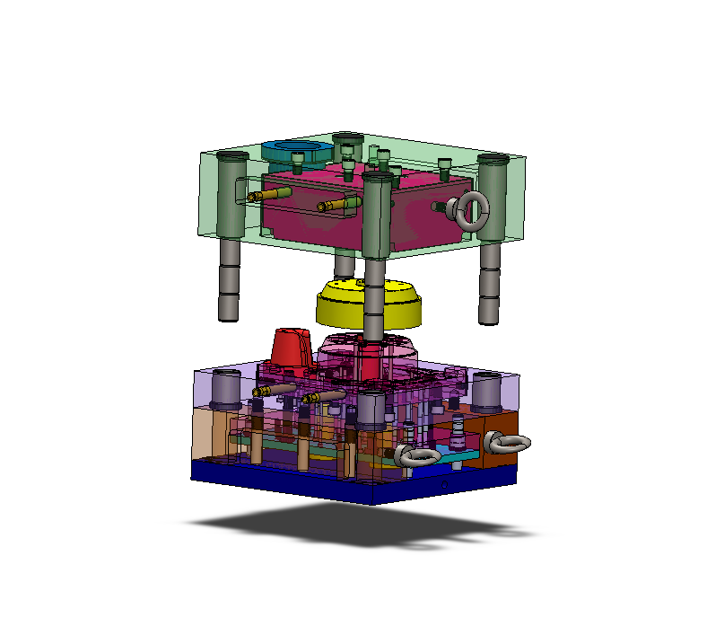
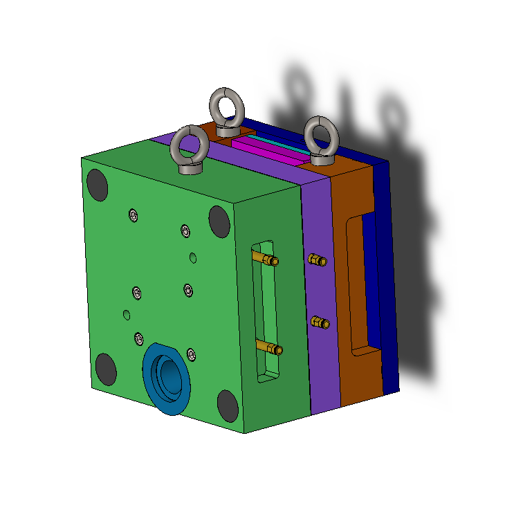
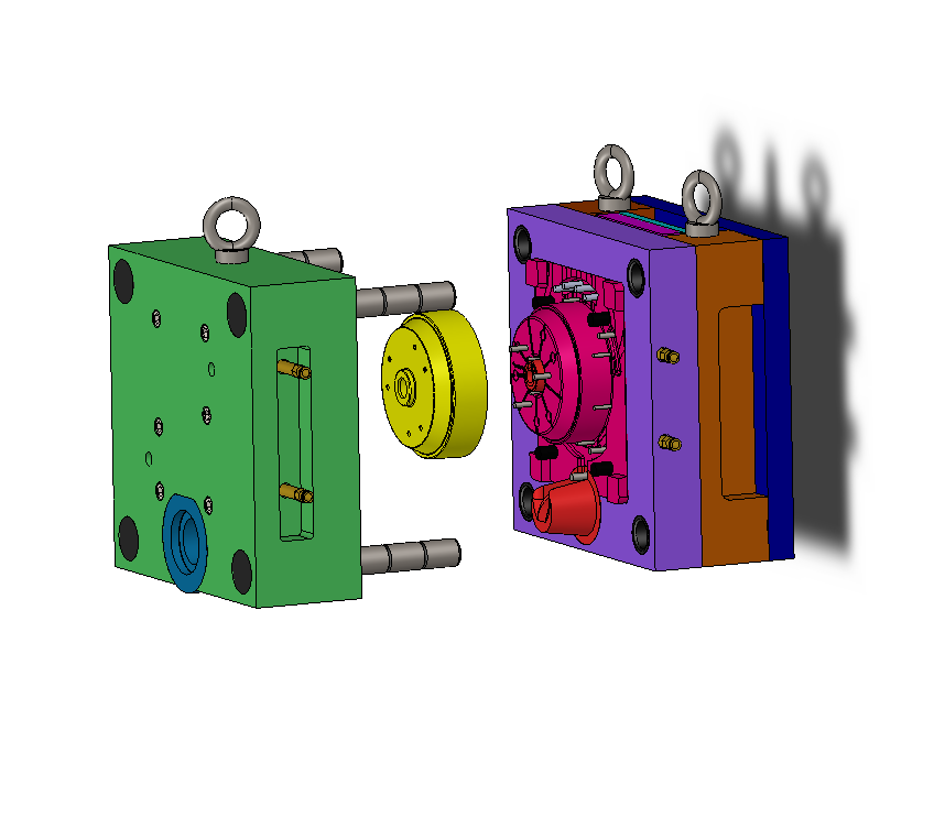
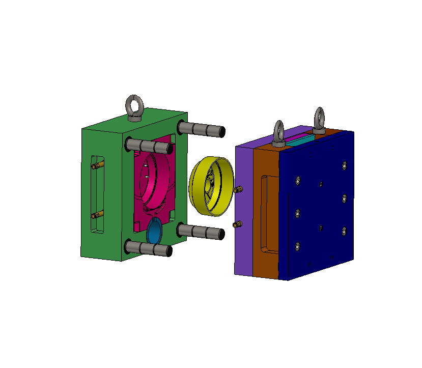
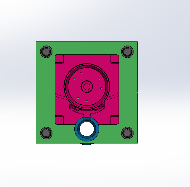
CAD Modelling
1. Perform Basic Calculations:
Tonnage Requirement:
We calculate the required tonnage of the die casting machine based on the projected area of the part and the material’s injection pressure. We also consider cavity pressure and include safety margins to ensure accuracy.Runner and Gate Area:
We calculate the runner and gate cross-sectional areas based on the material flow rate and required filling time, following NADCA guidelines to prevent defects like cold shuts or incomplete filling.Draft Angle Calculation:
We determine the appropriate draft angles to facilitate easy ejection, typically applying 1-3 degrees depending on the geometry and surface finish requirements of the part.
2. Initial CAD Modeling:
Create 3D Geometry of the Part:
We start by creating a 3D model of the part, ensuring that all critical features are accurately represented.Design Parting Line:
We establish the parting line according to NADCA guidelines, positioning it to minimize flash and allow easy separation of the die halves.Design Core and Cavity:
We design the core and cavity, considering shrinkage allowances and thermal expansion, and include pin cores where necessary, following NADCA recommendations.
3. Select Standard Components:
Guide Rods and Bushes:
We select standard guide rods, bushes, and alignment components that fit the die design. We use supplier catalogs to choose readily available components to ensure reliability and ease of assembly.Ejector Pins:
We choose standard ejector pins based on the part’s geometry and determine their optimal locations to ensure even ejection without damaging the part.
4. Supplier Consultation:
One-on-One Discussion:
We arrange a meeting with our supplier to review the die design and gather their input on manufacturability, material selection, and machining strategies.Design Adjustments:
Based on the supplier’s feedback, we make necessary adjustments to the design, such as modifying cooling channels, refining ejection mechanisms, or optimizing for cost and efficiency.
5. Final CAD Model Refinement:
Incorporate Drafts and Adjustments:
We apply the necessary draft angles to all relevant surfaces and make any additional refinements. We ensure that all features follow NADCA guidelines for die design.Optimize Runner and Gate Design:
We fine-tune the runner and gate system to optimize material flow, minimize turbulence, and ensure uniform filling of the cavity.Core Pin Design:
We finalize the core pin design, ensuring that the core pins are correctly positioned for forming holes and undercuts without compromising the casting or causing ejection difficulties.
6. Follow NADCA Guidelines:
Parting Line and Cavity Design:
We verify that the parting line, core, and cavity designs comply with NADCA standards to avoid casting defects and ensure smooth die operation.Cooling and Venting:
We incorporate the necessary cooling channels and vents in the die design to control the solidification rate and avoid defects like porosity or incomplete filling.
7. Final Review and Approval:
Internal Review:
We conduct an internal review of the completed CAD model, checking for potential issues related to assembly, manufacturability, or casting performance.Approval:
Once the design is finalized, we present it to stakeholders and the supplier for final approval before moving to the manufacturing stage.
This structured approach helps us ensure that the HPDC die design is optimized for performance, cost-efficiency, and manufacturability while adhering to industry standards.
Manufacturing
1. Manual Milling Machine Calibration:
We begin by calibrating the manual milling machine to assess the tolerance range and improve the accuracy of the machining process.
To enhance the locking mechanism, we adjust the gibs of the X, Y, and Z axes, ensuring smoother movement and improved stability during operation.
2. Perpendicularity and Straightness Testing:
We use a granite square to test the perpendicularity of the milling machine, ensuring that the machine’s axis alignment is precise.
A straight edge is used to check the straightness of the machine table, verifying that there are no deviations that could affect the machining process.
3. Tramming the Machine Head:
Before machining each part, we check the tramming of the milling machine’s head to ensure it is perfectly aligned with the table, preventing any angular errors during cutting.
This step is crucial for maintaining consistent accuracy across all parts.
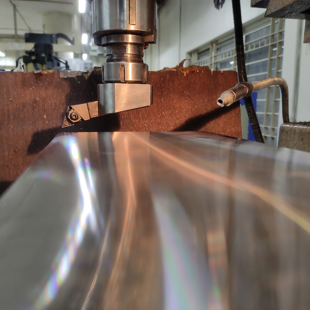
4. Runout and Polishing:
We measure the runout of the machine’s spindle collar to detect any deviations that might affect the cutting performance.
If necessary, we smooth out any imperfections by applying precision polishing, ensuring that the spindle operates without excessive runout or vibration.
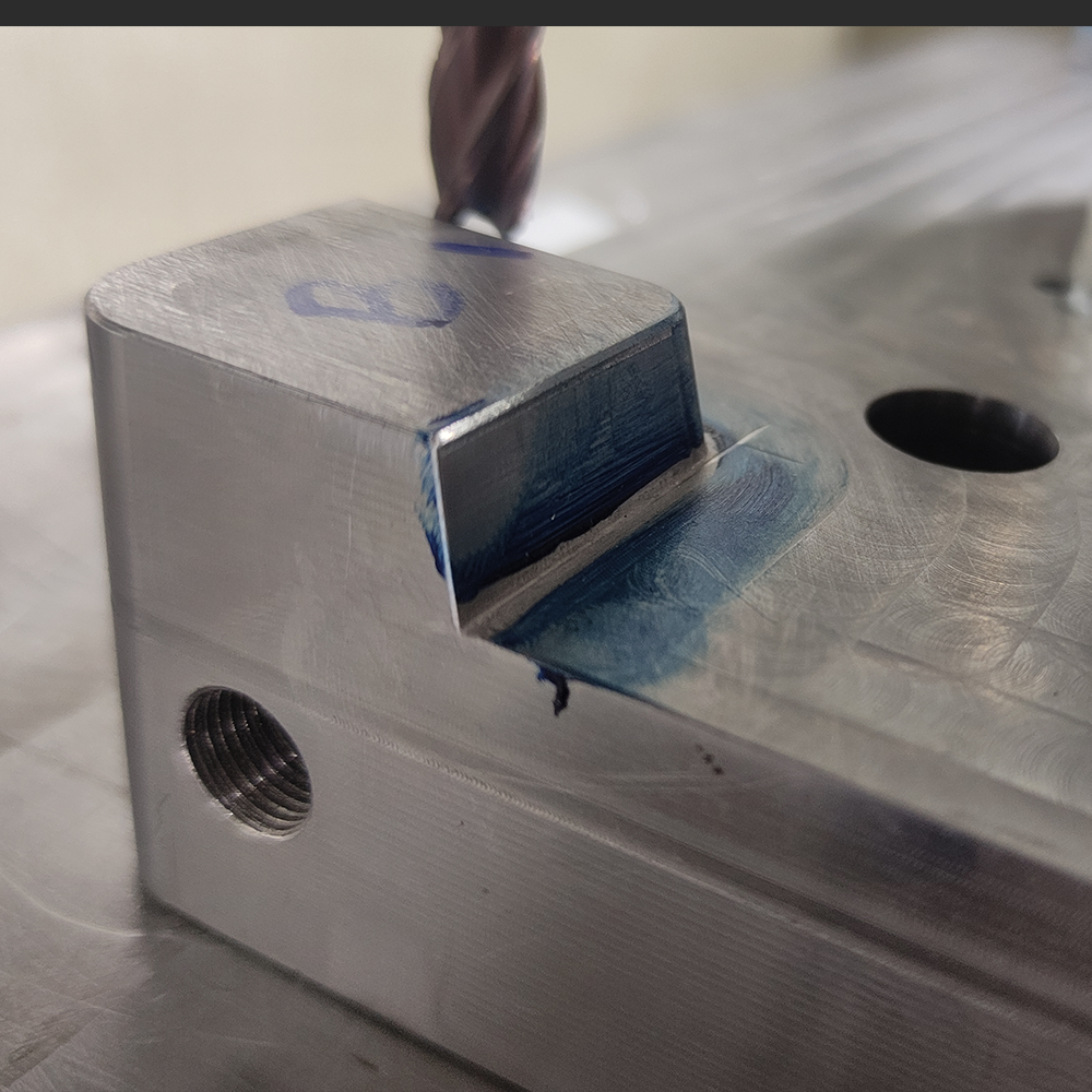
5. Profile Cutting on CNC:
Profile shapes are cut on CNC machines to ensure high precision and accuracy. The CNC process allows for intricate geometries that are difficult to achieve with manual machining.
6. Heat Treatment:
After the initial CNC cutting, we heat-treat the components to achieve a hardness of 48 HRC, enhancing the wear resistance and durability of the die components.
Post-heat treatment, the parts are machined again to final tolerances, ensuring that any distortions caused by the heat treatment are corrected.
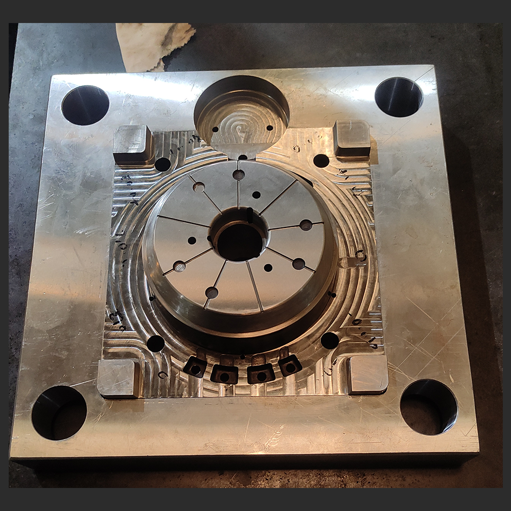
7. Jig Boring for Housing:
The housings are jig bored to achieve precise alignment of critical holes, ensuring accurate placement of components in the assembly.
Guides are then press-fitted into these jig-bored holes, securing the alignment and proper function of moving parts.
8. Dimensional Inspection:
All machined parts are measured using Coordinate Measuring Machines (CMM) and height gauges to ensure they meet the required tolerances and design specifications.
This step ensures that each component complies with the dimensional requirements before proceeding to assembly.
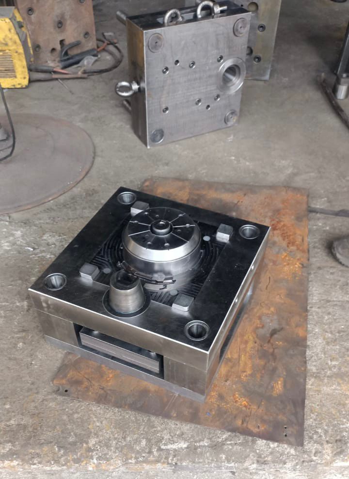
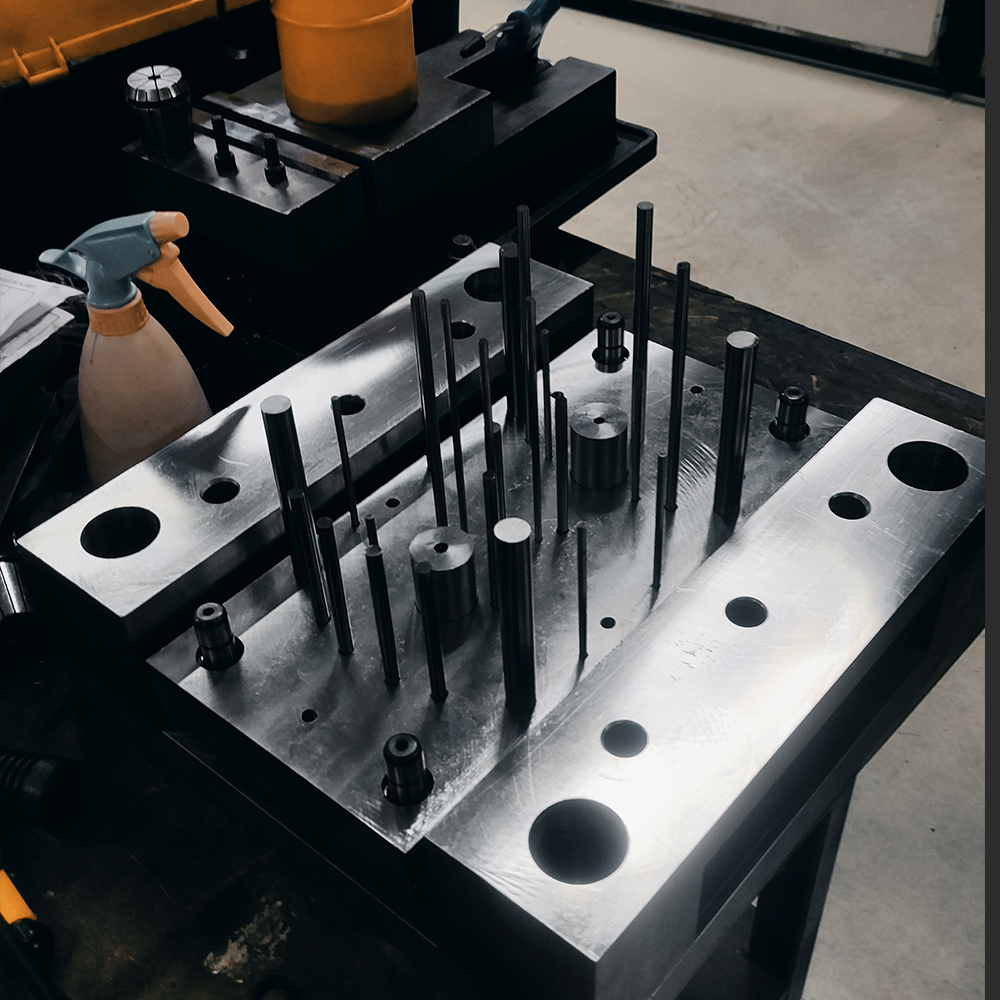
9. Final Assembly:
Once all parts have passed the inspection process, we proceed with the final assembly of the die.
Careful alignment and fitting are ensured during assembly to guarantee that the die functions smoothly and meets performance expectations.
Production
Die Polishing:
- After assembly, we send the die for polishing to achieve a smooth and precise surface finish.
- Polishing helps ensure the die’s cavity allows for easy ejection of the parts and contributes to the overall quality of the castings.
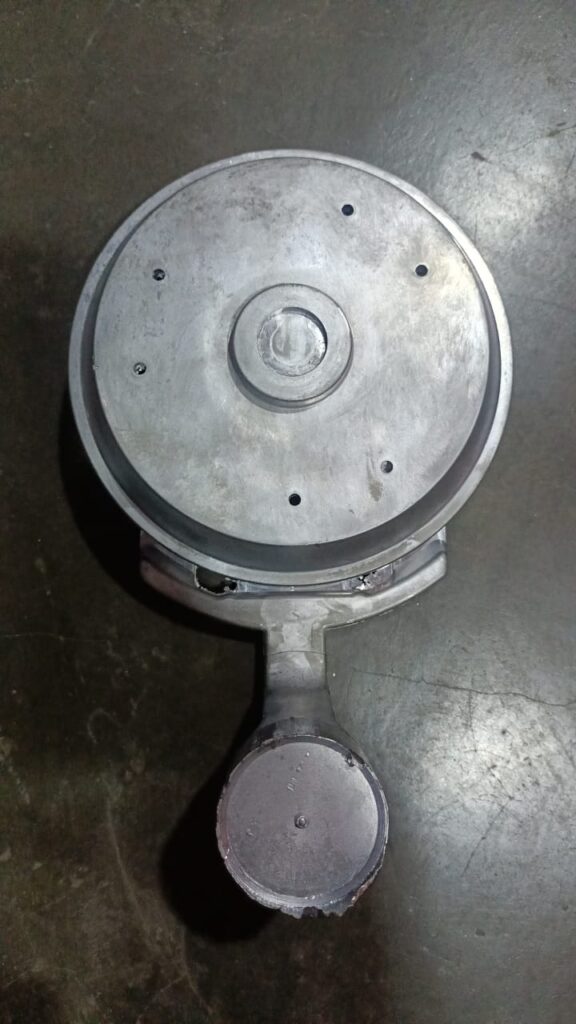
Trial Runs:
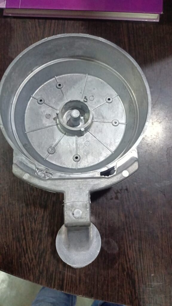
- Once polishing is complete, we perform trial runs by casting test parts to evaluate the die’s performance.
- During these trials, we closely inspect the parts for any defects, dimensional accuracy, and surface quality.
Issue Identification and Re-machining:
- If any issues arise, such as surface defects or dimensional inaccuracies, we identify the root cause.
- Basic re-machining is performed to address these issues, ensuring the die is corrected before full-scale production.
Optimization of Settings:
- We fine-tune the machine settings, such as injection speed, pressure, and cooling time, to optimize the die’s performance.
- Proper settings are established to ensure consistent and defect-free production in future runs.