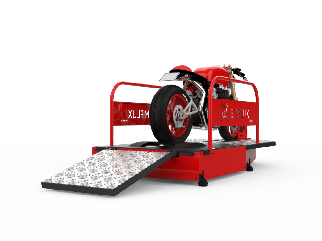
To design and develop a low-cost Inertia Dynamometer for EV manufacturers and educational institutions, enabling power and torque mapping at the wheel. This system helps diagnose and improve vehicle performance while allowing comparative studies between different vehicle systems, advancing research and education in EV technology.
Requirements
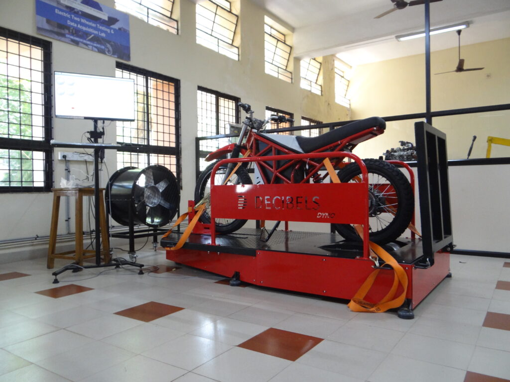
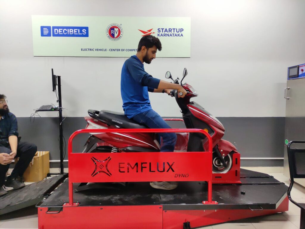
Test bench for two-wheeler
Able to accommodate wheelbase from 900mm to 1700 mm
Real time data capturing
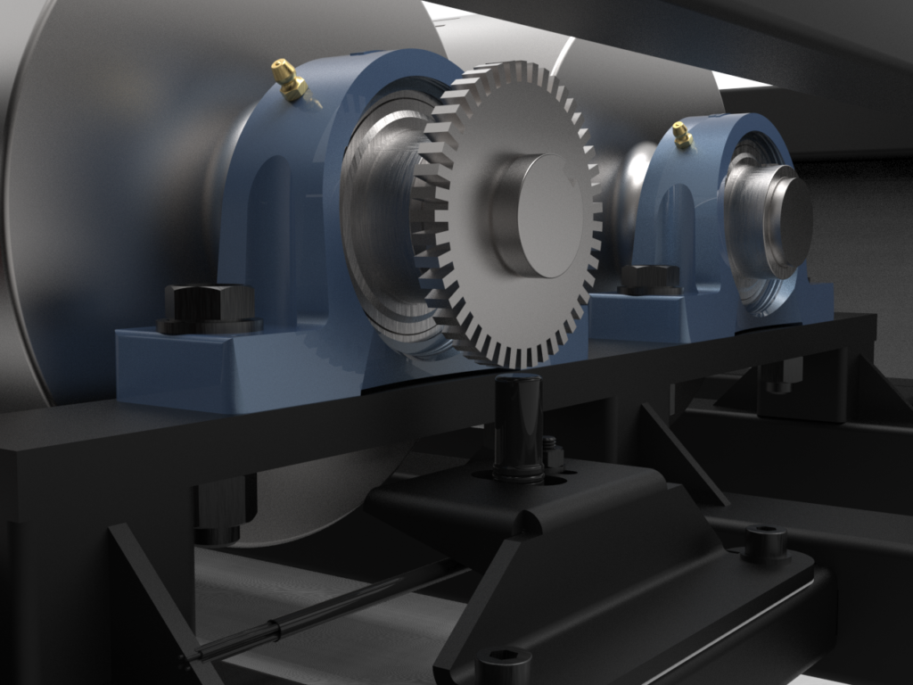
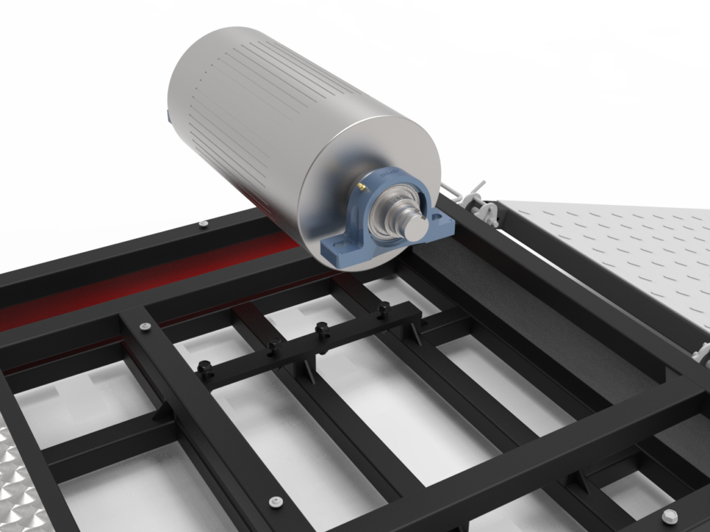
Should have enough moment of inertial
Stiff frame
Ensure user safety while testing.
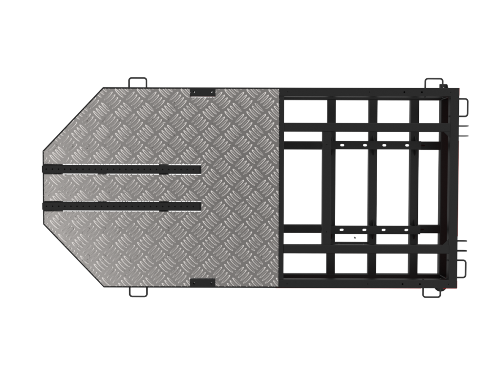
Tie down and lifting points.
Capable of adding a motor for upgrading it to Chassis Dyno
Process Steps
Outline the project objectives, deliverables, and requirements.
Learn new skills if the project requires some work done which is not covered by existing resources.
Establish a clear timeline with milestones, including design completion, prototype testing, and final delivery.
Calculate the budget, covering design, prototyping, materials, manufacturing, and testing costs.
Identify and confirm suppliers for materials, components, and services needed for the dynamometer.
Assign tasks to team members, covering design, testing, procurement, and manufacturing.
Identify potential risks, such as supply chain delays or technical issues, and develop mitigation plans.
Complete all necessary compliance checks before finalizing the project
CAD Modelling
Contacting manufacturing supplier for the project and asking their input to insure quick easy and cheap manufacturing solution.
Designed the frame body using WELDMENT in SolidWorks and simultaneously using tab and slot method for easy Tube assembly and welding.
Ensuring ergonomics and safety for the operator while testing the vehicle.
Modal analysis for stiffing the frame.
Packaging and transportation consideration so that final shipping cost can be reduced while maintaining a robust strength.
Preparing detail drawings for the supplier for Tube and Sheetmetal Laser cut, welding and powder coating.
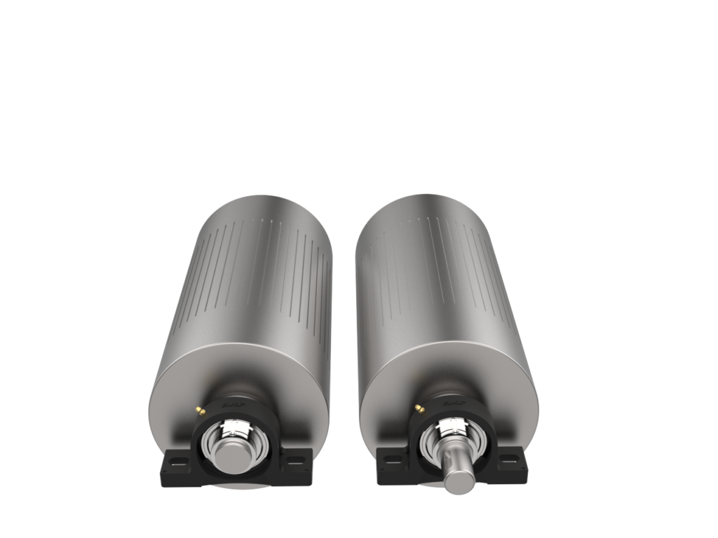
Selecting Appropriate Bearing to handle dynamic loading and designing rollers mating shaft with appropriate tolerance for assembly.
Designing mounting plate for sensor with objective to damp the in-frame vibration to avoid any data loss.
Software
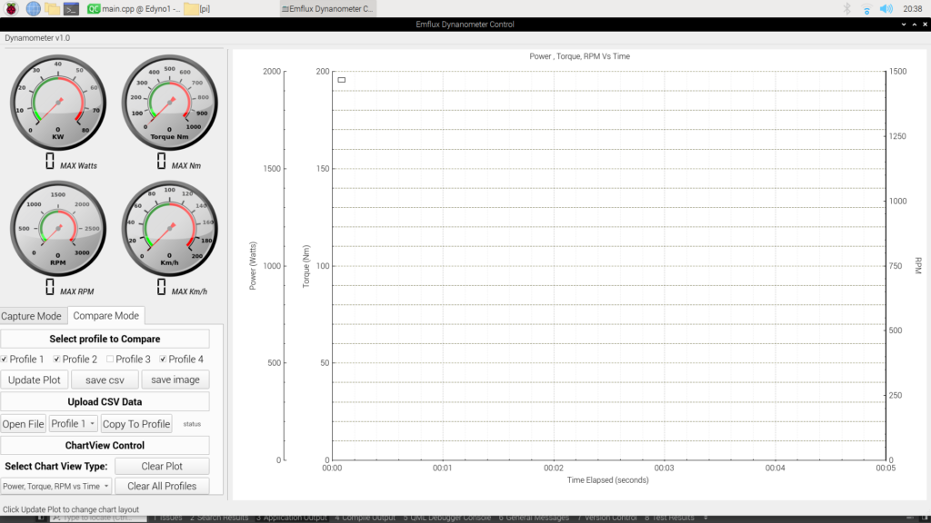
Determine the key features and functionalities required for the GUI, such as data display, real-time monitoring, user inputs, and integration with the dynamometer system.
Install the necessary tools, including the QT framework and a C++ compiler on Raspberry Pi
Use QT Designer to create the visual layout of the GUI, arranging widgets like buttons, text fields, graphs, and data displays.
Ensure the layout is intuitive and user-friendly, catering to the specific needs of the dynamometer data acquisition.
Write the C++ code to handle data acquisition from the dynamometer’s sensors and hardware.
Integrate the backend logic with the GUI, ensuring that real-time data is properly captured and displayed on the interface.
Set up communication protocols to transfer data from the dynamometer to the GUI, such as using serial communication or networking depending on the hardware setup.
Ensure data is processed and updated in real-time within the GUI.
un extensive tests to ensure that the GUI functions correctly, including stress tests for real-time data handling and error handling for invalid inputs.
Debug any issues related to data acquisition, user interface responsiveness, or hardware communication.
Optimize the GUI for performance, minimizing latency in data acquisition and improving responsiveness.
Finalize the design and code, ensuring the application is stable and user-friendly for its intended use.
Package the application for deployment, ensuring compatibility with the target operating system and hardware.
Provide documentation or user instructions for operating the GUI with the dynamometer.